


High Voltage Switchboard Fault Logger
Fault Triggered Data Logging System for 6.6 KV Medium Voltage Marine Switchboards
Design, Manufacturing and Installation of a Fault Triggered Event Data Logger System for use With 6.6 KV Medium / High Voltage Switchboard on Commercial Ships
With respect to the original OEM design of the ship’s high voltage switchboard and its control systems, there are multiple channels / circuit branches through which a vacuum circuit breaker (V.C.B.) of a running generator can be tripped during a fault event. And this could lead to a possible blackout of ship’s power.
In many recently reported cases ship crew have faced difficulties in determining the root cause and immediate cause for the VCB to be tripped during a blackout (this observation is applicable for both cases where the crew could immediately re-store the power, and also in the cases where they could not do so for many embarrassing hours).
Observations
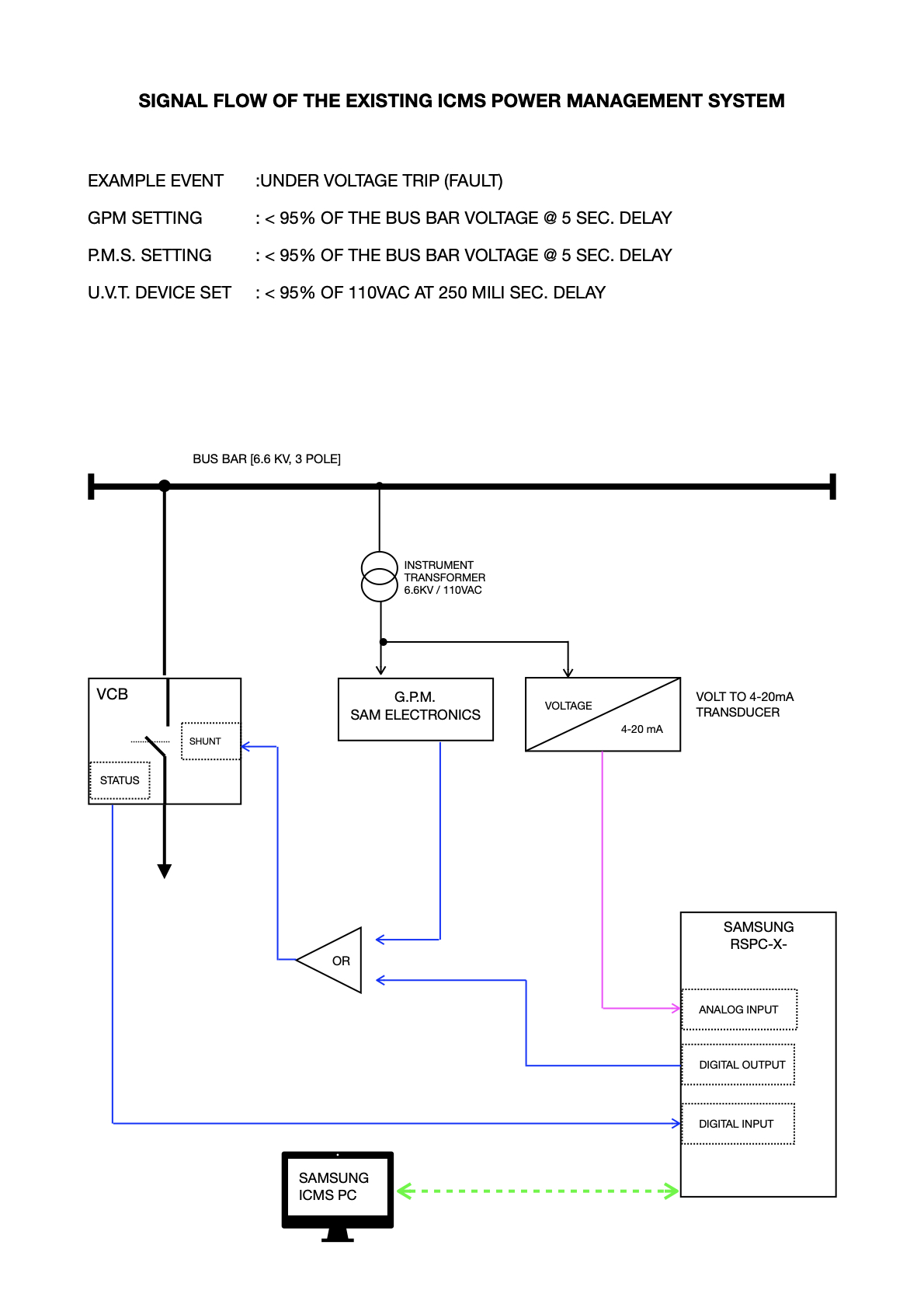
- During preliminary incident investigation soon after a blackout, the ship’s crew relying only on the alarm log of the integrated control & monitoring system (ICMS).
- But, due to the data transfer speed limitation of ICMS, there is always a delay or a time-lag in capturing essential parameters especially during a high speed transient event which could happen within few milliseconds (for example U.V.T. operation is set at 250 milliseconds).
- The location of high voltage switchboard, the remote terminal unit of the ICMS (RSPC-X-) and also, the ICMS main computer is three different locations which is far away from each other.
- This results a time-lag of capturing high speed data or parameters and further delays the output action and the alarm logging.
- There is no provision to identify if the VCB is tripped due to the function of under voltage trip device (U.V.T).
- No graphical means to provide side-by-side comparison of real time parameters (both digital & analog values).
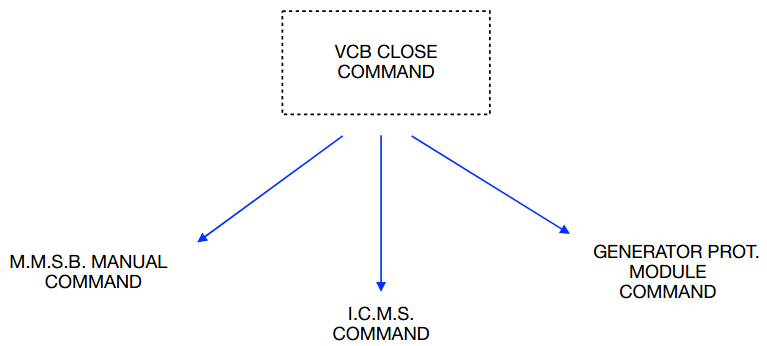
Channels / Circuit Branches (Main) That Could Command to “Close VCB”
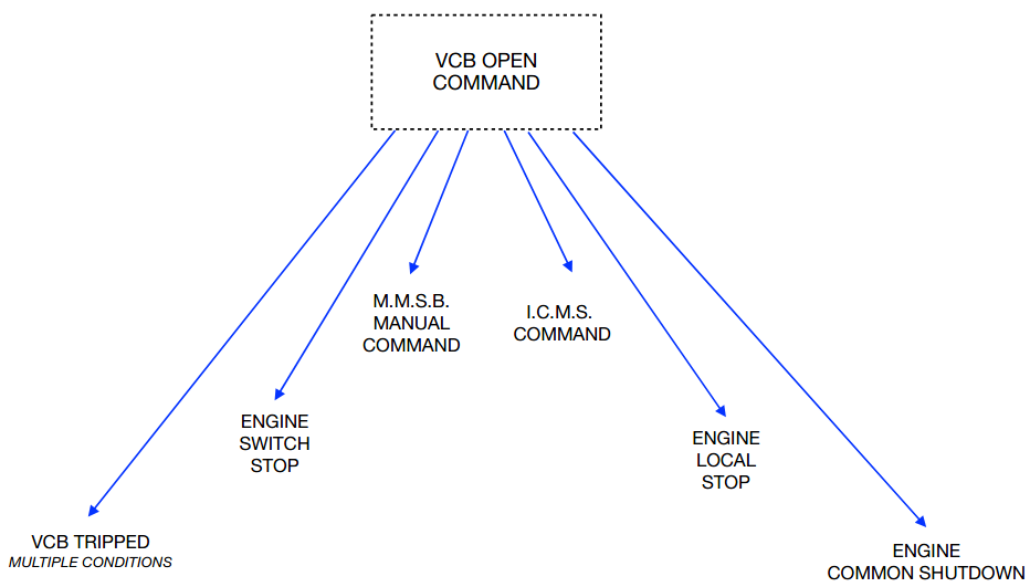
Channels / Circuit Branches (Main) That Could Command to “Open VCB”
Advantages of Fault Triggered Data Logger as a Troubleshooting Tool
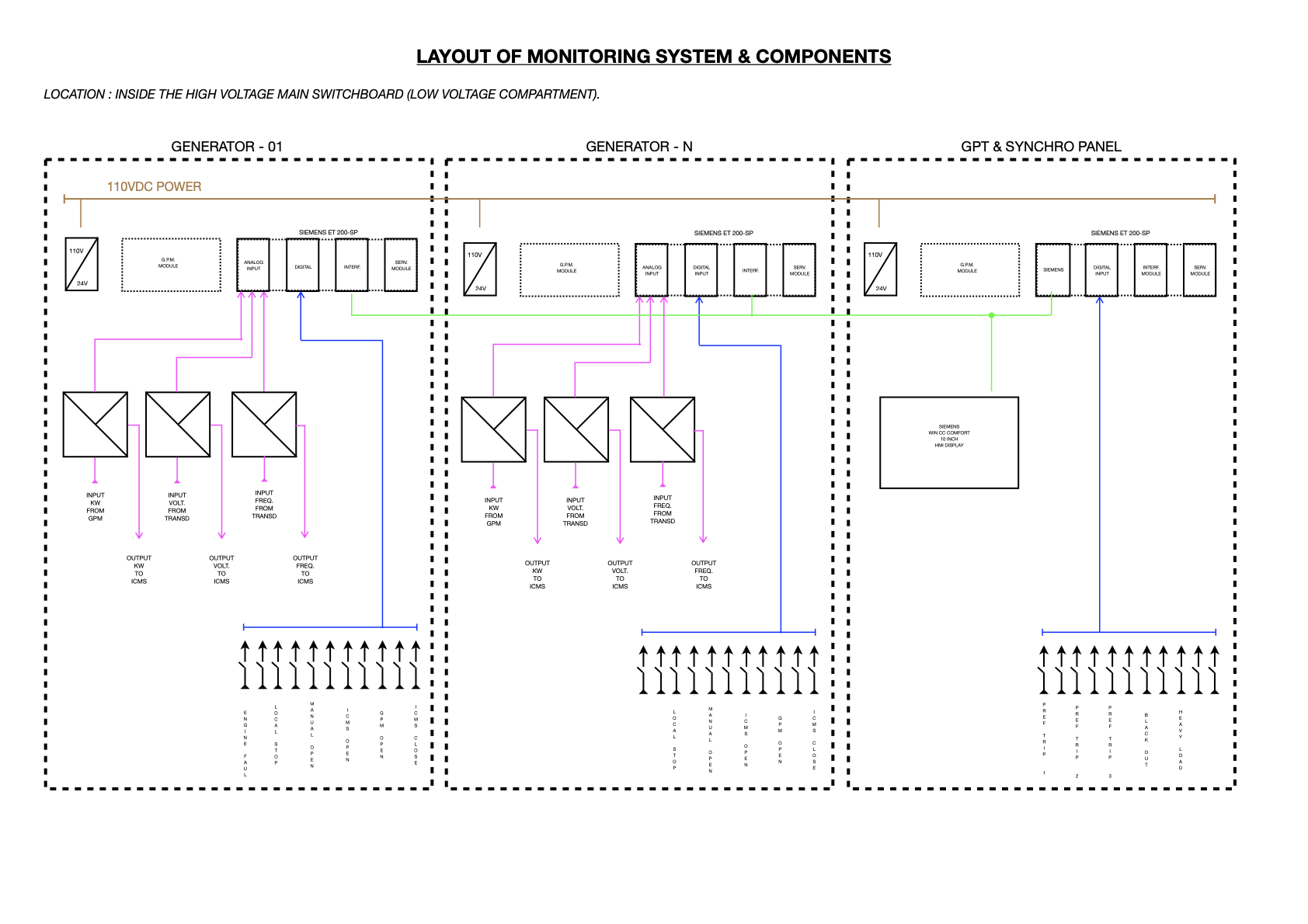
- System is placed inside the low voltage compartment of the switchboard, hence data / parameters directly fed from the HV switchboard to the monitoring equipment.
- Data capturing is faster, and also able to capture high speed transient faults up to 100 milliseconds.
- Provision is available to monitor the Under-Voltage Trip Device function. Thereby to notify if the VCB is tripped by the U.V.T.
- Monitoring system is independent and totally isolated from the existing control and safety circuits of the HV switchboard.
- No interference with the operation, monitoring and the safety functions of the VCB.
- Compact components can be easily mounted inside the existing enclosure. Also, can be connected to existing 110VDC power supply unit.
- Highest reliability thanks to the siemens (Germany) components.
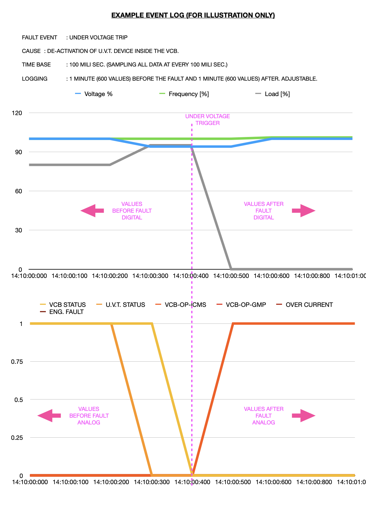
- Captures and stores multiple parameters simultaneously. When a fault trigger is active relevant parameter values are graphically displayed on a 10-inch-wide colour display 01 minute before and 01 minute after the incident (time frame can be changed in configuration).
- Data can also be downloaded on to a pc for evaluation.
- Easily configurable and expandable according to the future requirements.
- Economical cost.
SPARE PARTS LIST
**Considered for 01 Switchboard With 05 Generator Panels and 02 Synchro Panels
- SIEMENS, ET-200 SP, BASE MODULE = 07 PCS
- SIEMENS, ET-200 SP, SERVER MODULE = 07 PCS
- SIEMENS, ET-200 SP, 8 X DIGITAL INPUT MODULE = 14 PCS
- SIEMENS, ET-200 SP, 4 X ANALOG INPUT MODULE = 05 PCS
- SIEMENS, SCALANCE, 8-PORT, MANAGED ETHERNET SWITCH = 01 PC
- SIEMENS, S7-312 CPU = 01 PC
- SIEMENS, TP-900 COMFORT MULTI COLOUR HMI PANEL = 01 PC
- PHOENIX CONTACT, 3-WAY SIGNAL ISOLATOR, FOR 4-20mA ANALOG SIGNALS = 15 PCS
- SIGNAL CONDITIONING RELAY, DC CURRENT TO 4-20mA = 07 PCS
- INTERFACE RELAY, 110VDC, 2-P-C-O = 25 PCS
- SIEMENS, INDUSTRIAL ETHERNET CABLE, MARINE TYPE = 20 MTRS
- RJ-45 NETWORK JACKS, RIGHT-ANGLED = 15 PCS
- DIN RAIL MOUNT FUSE CARRIERS = 14 PCS
- STANDARD DIN MOUNTING RAILS (IN METERS) = 07 PCS
- FLEXIBLE CONTROL CABLE, 0.75 SQMM (IN METERS) = 05 REELS
- FLEXIBLE CONTROL CABLES, 1.5 SQMM, BLUE (IN METERS) = 01 REEL
1/ 41, Cardinal Cooray Road, Dikowita, Hendala 11300, Wattala, Sri Lanka.
Telephone : +94 112 948 533Hotline : +94 711 397 922
E-mail info.marine@horizonelectrotechnics.com info.automation@horizonelectrotechnics.com
Webwww.horizonelectrotechnics.com